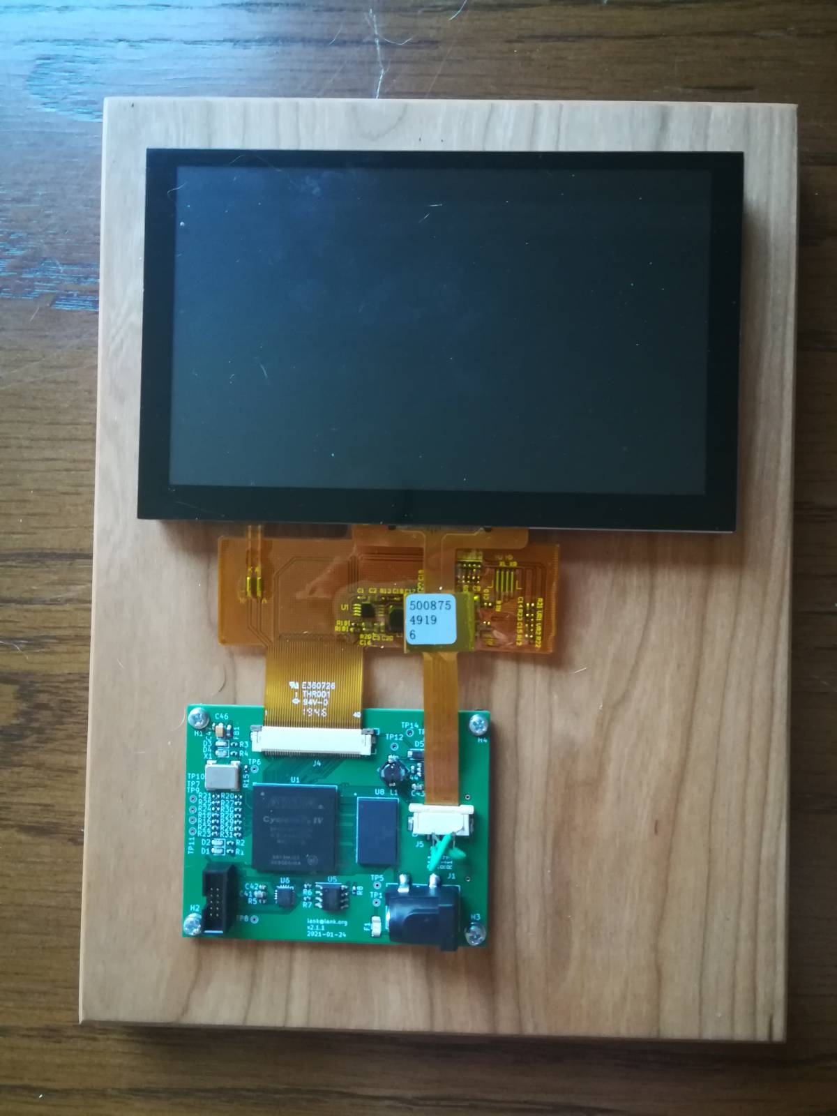
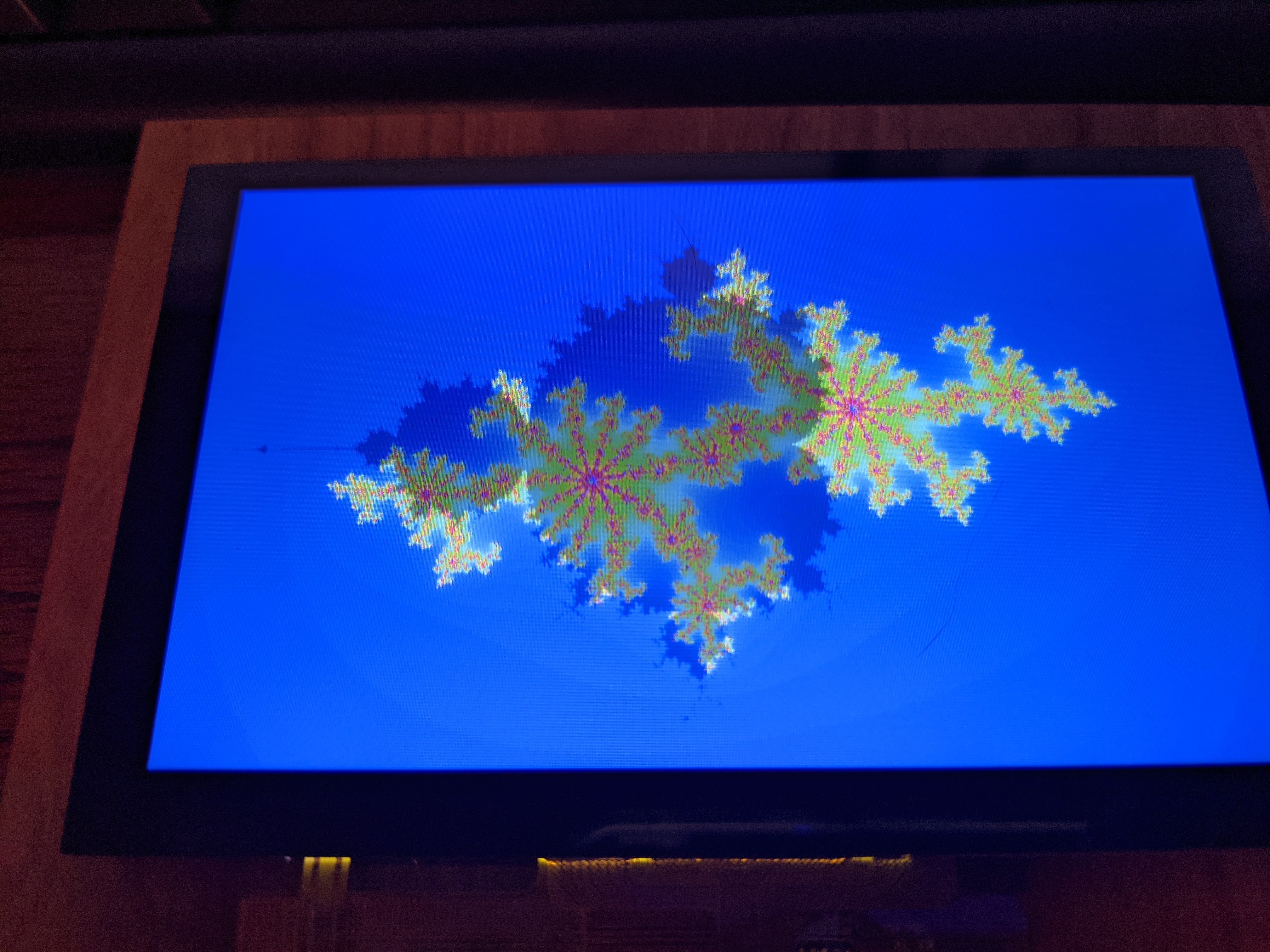
A custom Cyclone IV board interfaces with TFT LCD panel, capacitive touch controller, SDR SDRAM. The FPGA superimposes a Julia set on the Mandelbrot set. Touching the screen chooses the set point z0.
Check out Malin Christersson’s julia set visualizations here. This is basically an implementation of the first demo on that page. One thing that should be clear is that there’s no need for an FPGA to do this; it’s in fact exactly the wrong approach. This project was a solution in search of a problem: I started with a Cyclone II and an LCD with no application in mind and it evolved from there. I got to use it as a vehicle to learn about FPGAs, verilog, and push my PCB layout and assembly capabilities.
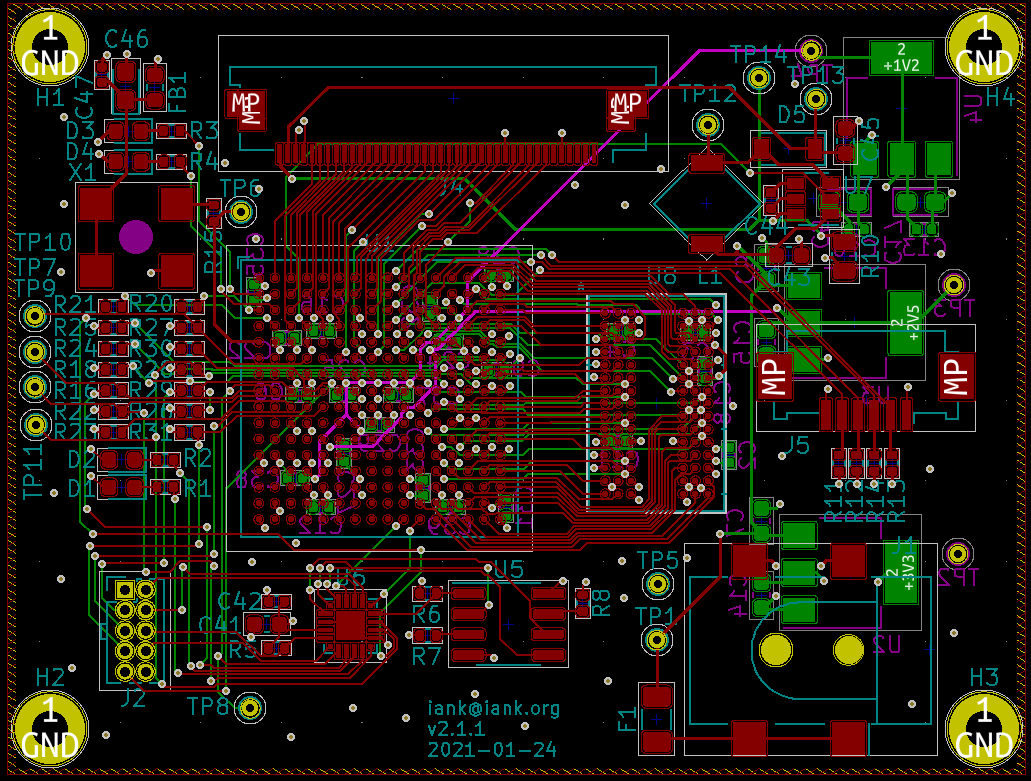
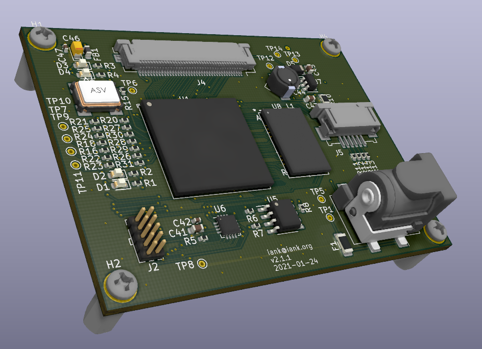
All of the design files can be found on github at https://github.com/iank/julia_lcd.
Hardware
The final evolution of the hardware is a Cyclone IV FPGA, an external SDRAM, and a Silicon Labs EFM8 microcontroller used to configure the FPGA from a SPI flash. The LCD module contains a capacitive touch controller, broken out on the second, smaller, flex cable.
Verilog
The FPGA’s internal blockrams are not large enough to contain an entire frame, hence the external memory. Lines are loaded from memory during the blanking interval before they are needed. Otherwise when the memory bus is not in use the fractal can be computed. First the Mandelbrot set is computed as a binary image and the Julia set is overlaid upon it.
An i2c master is also implemented. This controls the touch screen. Upon receipt of a touchscreen interrupt, the coordinate is queried and this is used to set the z0 point for the Julia set.
Lessons learned
I’d never used an FPGA before this project. I spent a lot of time iterating on the Verilog here, and I learned a lot about what I could and could not do (as well as the memory bandwidth / LUTs I’d need to do it). This was also the first time I assembled a BGA part at home.
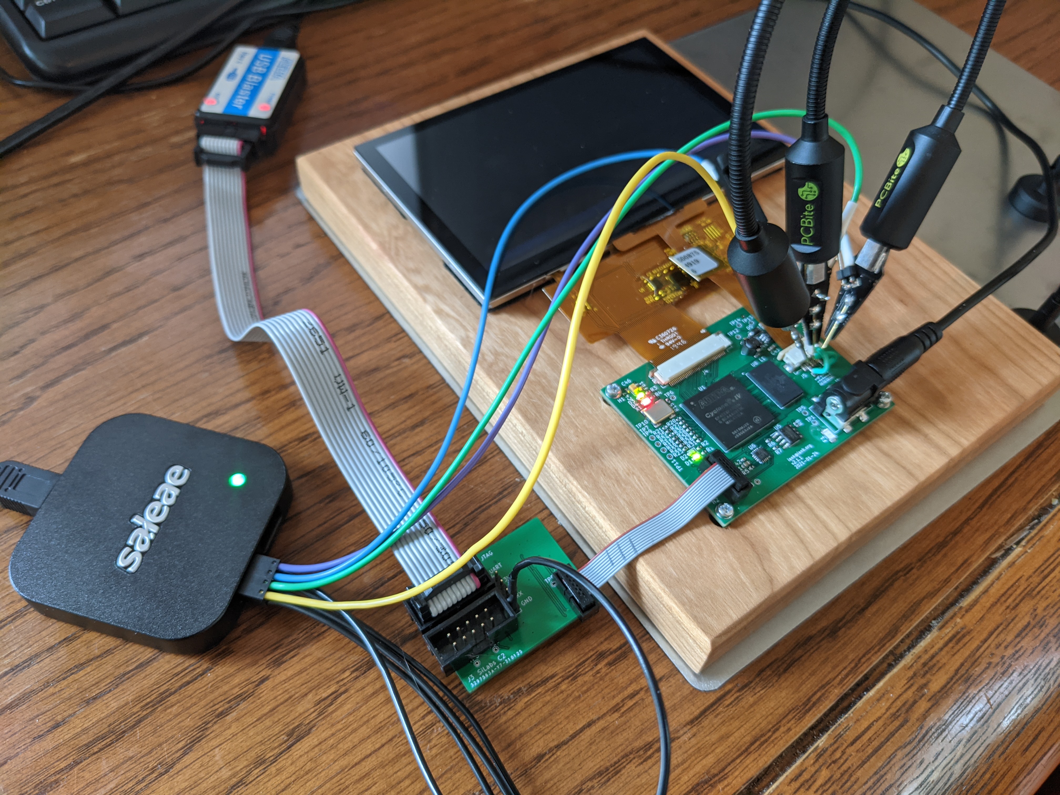
Using a separate debug/programming board was handy. In one spin I had tried using a board-to-board connector for this, which turned out to not be tenable without mechanical support. The IPC cable pictured above was easier to assemble and didn’t really take up more space.
FPGA debugging in-system is hard. Taking the time to set up simulation models/fixtures was worth it every time. First I wrote a mock LCD module that would output frames as png files during the simulation. That made clear some timing/alignment issues that just weren’t visible otherwise. Then I adapted a memory model from Micron for the specific part I used, which helped debug some memory issues.
Last modified on 2021-12-27