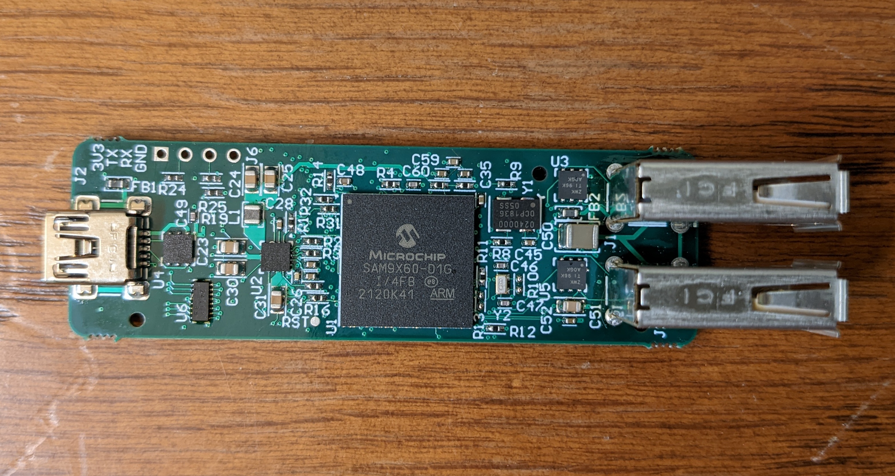
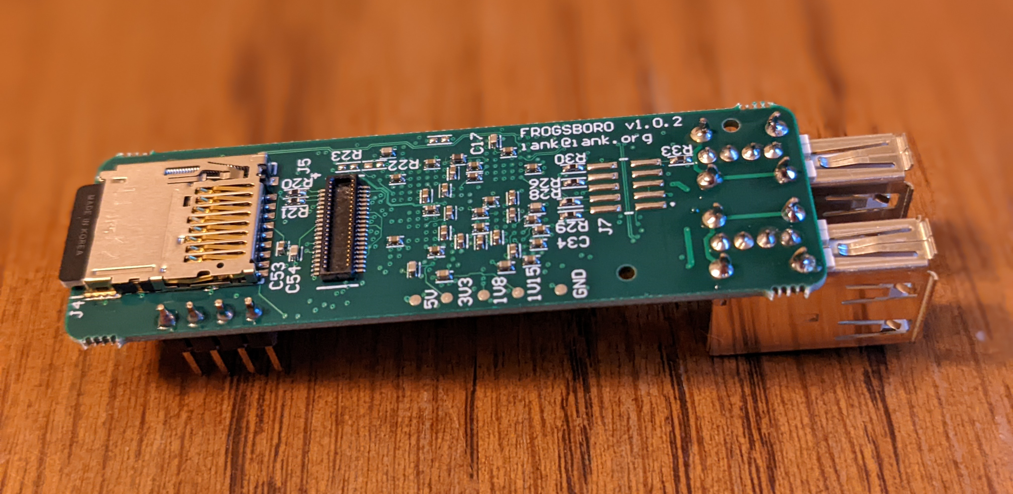
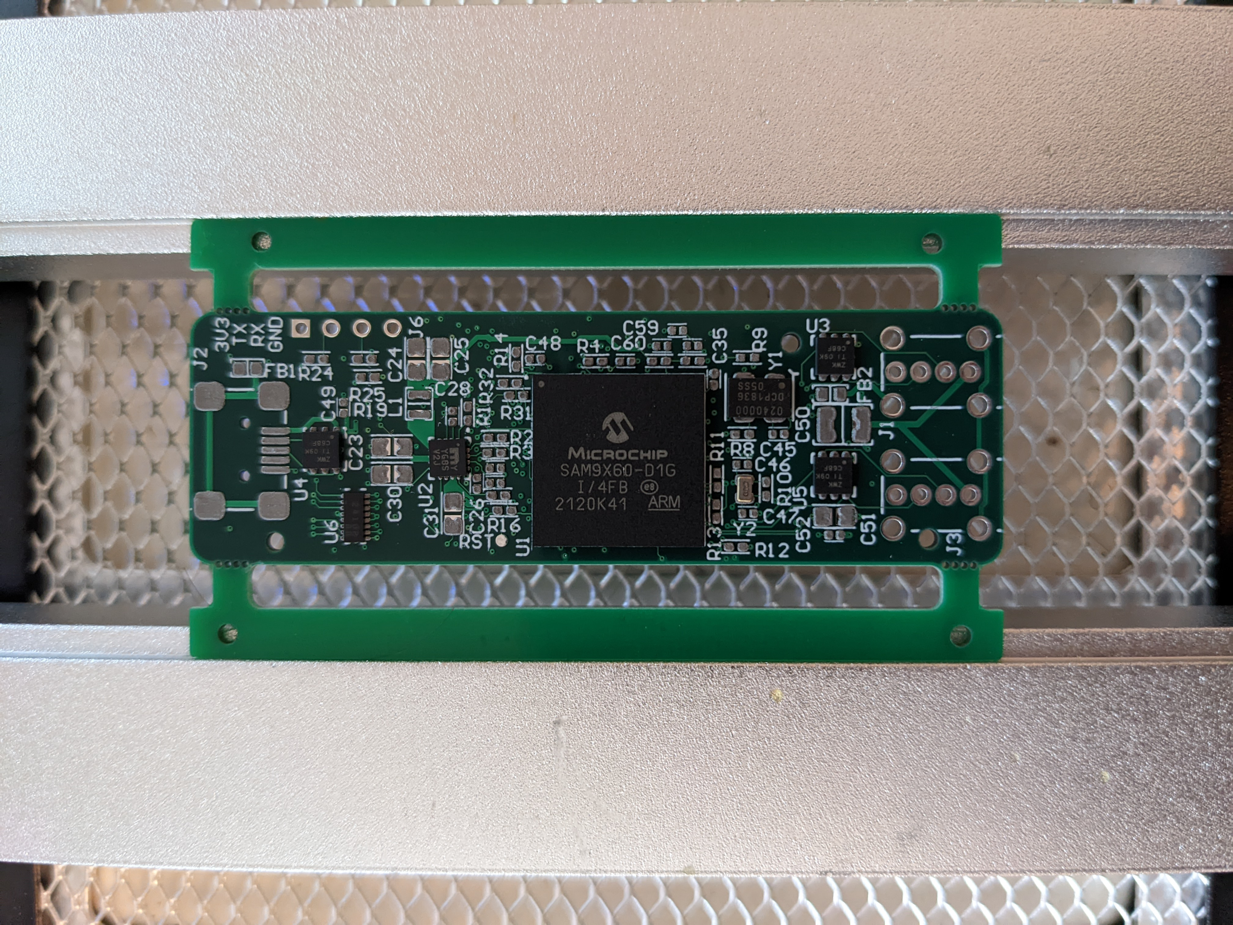
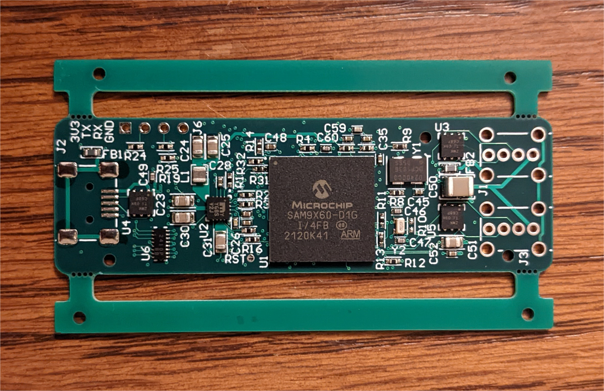
Another custom embedded Linux board. I recently did a free evaluation of Altium Designer and built this as a way to try it out. The design is based on the SAM9X60 SiP and has a USB device port, two USB host ports, a microSD card, and a low profile 40-pin expansion connector (following the Raspberry Pi pinout) which breaks out GPIOs and various other peripherals. It’s called FROGSBORO, which I guess is a moderate improvement over CATFOOD.
Design files: Schematic (pdf), BOM (pdf), Gerbers (zip)
Update 2022-04-17: Added a section on the stencil alignment fixture.
Layout
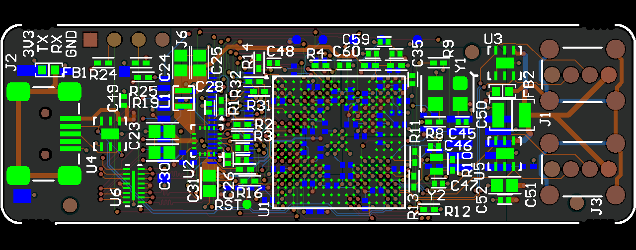
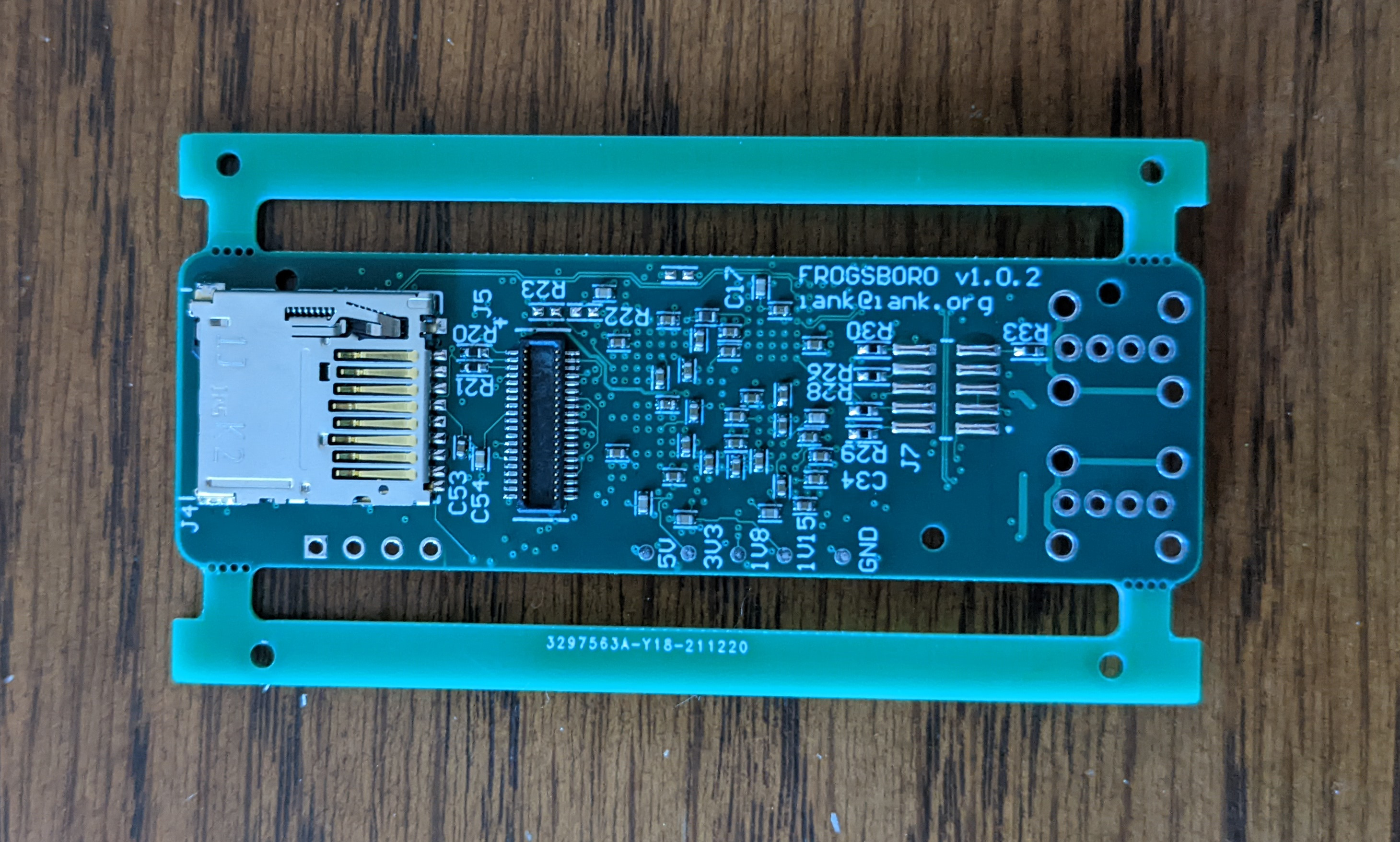
I used a six layer stackup from a low-cost fab. It measures 67mm by 21mm. A MIC2800 PMIC provides the three necessary voltage rails. An oscillator and a crystal provide the core clocks, there’s a DDR voltage reference, and the various connectors have ESD protection. (This is the first spin of the board; the 1.0.2 version number reflects some back and forth with the fab). The total cost for PCBs, stencils, and components was around $200.
Assembly
Stencil Alignment Fixture
I’m experimenting with a new alignment fixture for applying paste. In the past I’ve used scrap PCBs to frame the board and a masking tape hinge on one edge of the stencil (Video from JLCPCB, Tutorial from Sparkfun). This has worked well enough for me. It takes some time to line everything up and tape it down, but once set up it’s surprisingly repeatable. It’s stressful to set up for just a few boards though, and double-sided assembly is a pain since the setup needs to be elevated to apply paste to the second side.
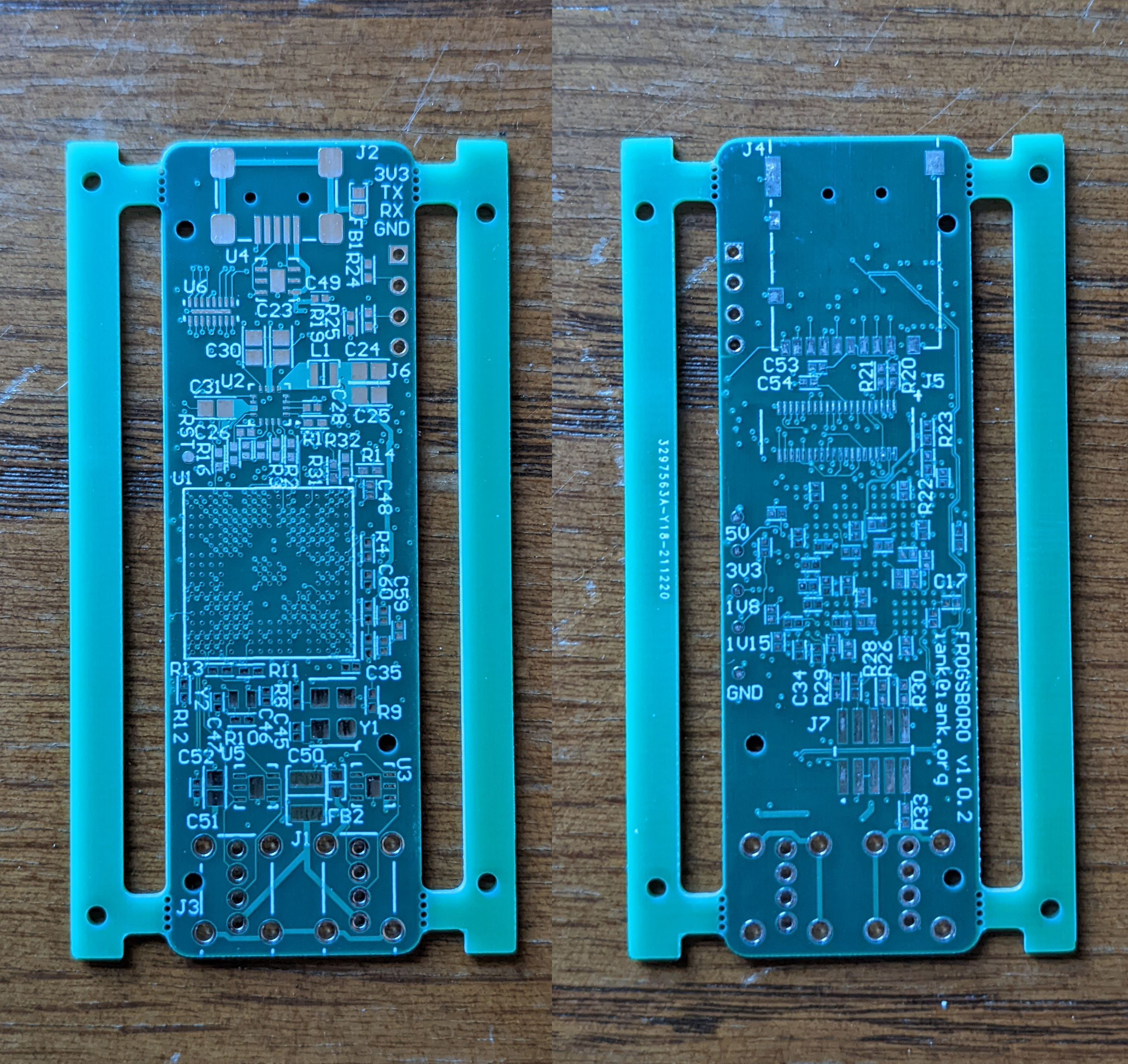
On this board I added breakaway rails with mouse bites1. The rails each contain two stencil alignment holes, which are just a non-plated through hole and a corresponding footprint on the paste layer. Since it’s not typical2 to have paste over holes I included a note to the fab to clarify that this was intentional. I then milled a fixture from a block of common pine.
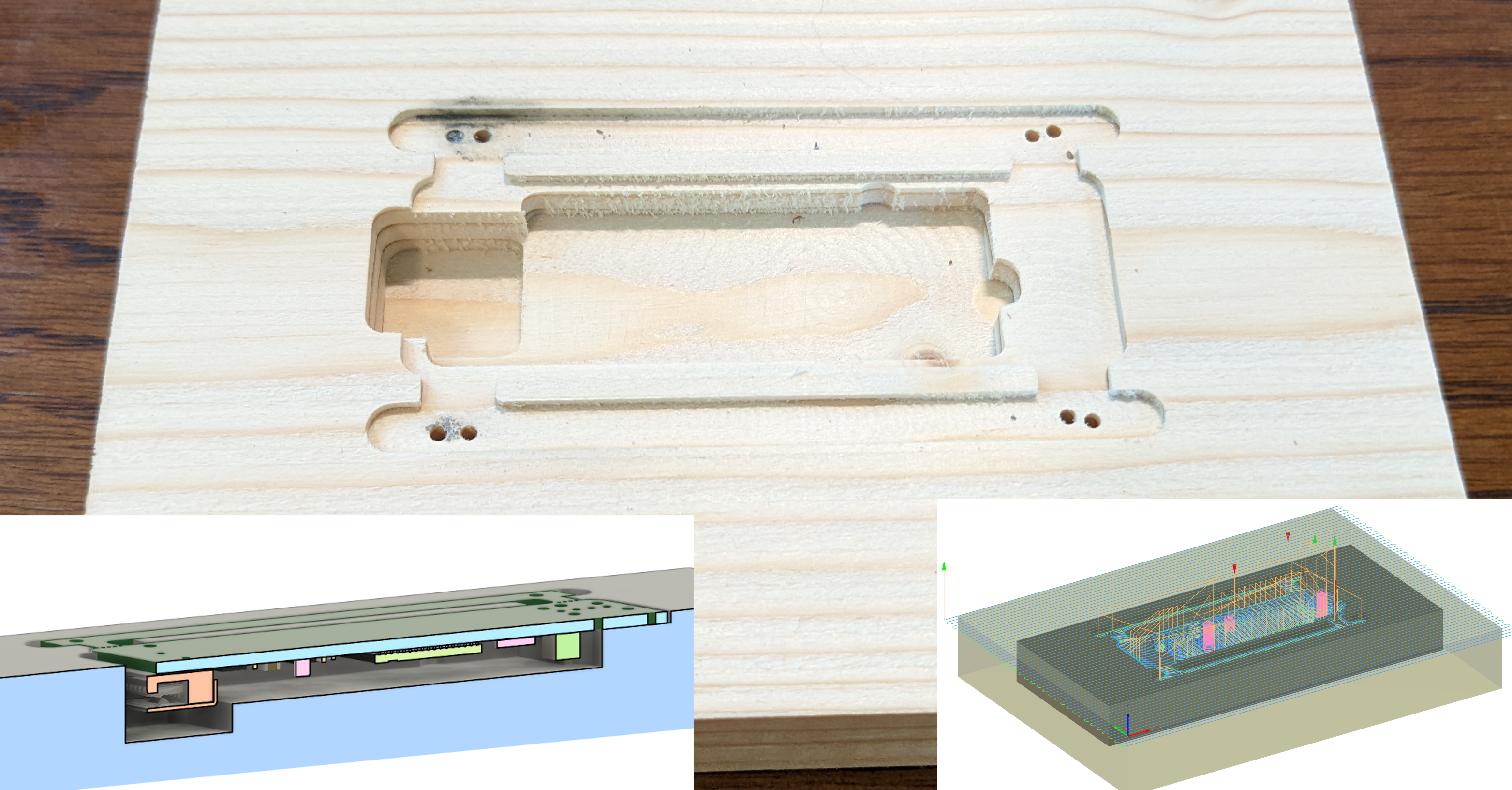
The board sits in a recess so that the surface is flush with the wood, the stencil can sit on top of both, and gauge pins are used to fix everything in place. There is also a cavity to allow clearance for the top side components when applying paste to the bottom side.
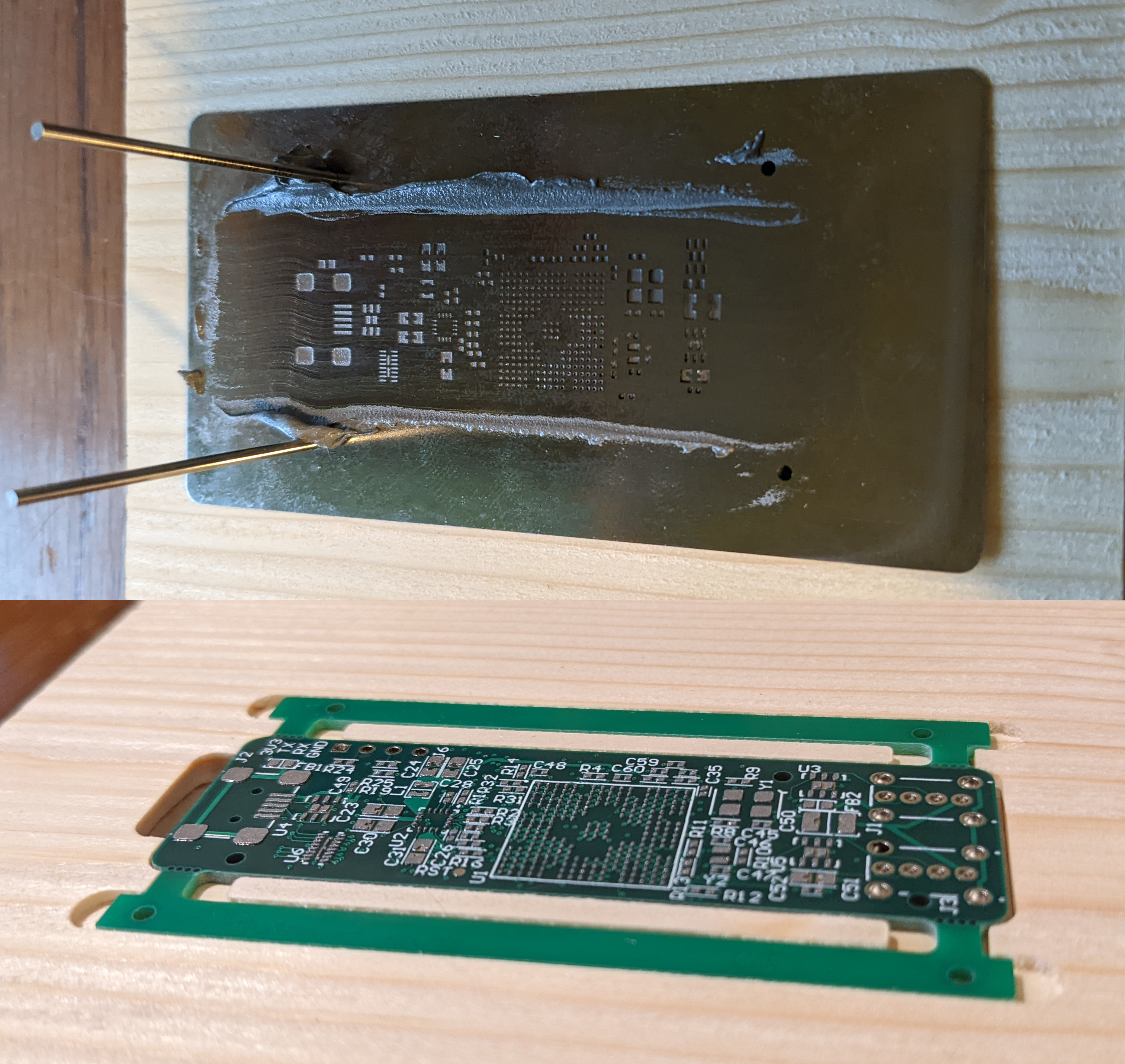
There’s obviously a different sort of setup time involved in the CAD/CAM and milling the fixture. In the end though it was pleasant to use, the alignment felt solid, and the resulting paste application was crisp and consistent. I won’t use this for every board, but for double-sided boards and/or boards with small feature sizes it’s a nice tool to have.
Component Placement and Reflow
Once paste was applied I used my normal method for assembly. I use my preheater (turned off) to clamp the board while I place components..
… and then reflow with the preheater around “300°C”3 and very low flow rate hot air at 350°C.
For the bottom side, I keep the preheater lower (“100°C”) and use the same hot air settings. Through hole parts are the final step. They need thermal relief as I don’t have the board preheated when soldering these.
Software

I didn’t have to do much here. I was able to boot a demo image form the sam9x60-ek evaluation kit. I used linux4sam-buildroot-sam9x60ek-headless-2021.10.img. The device tree should ideally be modified to remove peripherals that aren’t present (e.g., Ethernet), but leaving it as-is doesn’t cause a problem.
I used an FTDI cable to access the UART for first boot. I then modified the inittab to load g_serial and start getty on ttyGS0. This lets me use the SAM9X60 USB device port, which is also powering the device, as a serial console.
Update 2022-11-10: I’ve since built a yocto layer for this board. See frogsboro-firmware
Thoughts
- This was my first six layer board. The extra routing layers were nice, but in this case less useful than they could be. At this budget I’m stuck with (relatively large) through vias meaning some areas can quickly become Swiss cheese on every layer.
- I like this PMIC. Absolutely happy to use one part to provide all of the voltage rails when I can get away with it.
- The fab I use has a coarse silkscreen print resolution. This isn’t the first board where I’ve had to delete some reference designators to make others fit. But the resulting silkscreen is still crowded to the point of ambiguity. I may start leaving designators off for most passives by default and only including the ones that I think may be frequently referenced.
- In the future it would be better to place the mouse bites recessed back from the board edge so that the broken-off pieces don’t protrude.
I used 0.5mm diameter non-plated holes, with 0.75mm from center to center and 0.5mm clearance from the outside hole edges to board edge. There is no copper on any layer on the rails. ↩︎
Aside from paste-in-hole, which I think is still fairly uncommon. ↩︎
This and other temperature settings I’ll mention for this preheater only loosely correspond to the actual temperature the board reaches. It’s an IR heating element an inch or so underneath the board and the control system, such as it is, controls the element temperature, not a temperature probe on the board. ↩︎
Last modified on 2022-01-08